Aluminium Casting · Creative Alucast
High Pressure Die Casting
Tolerance: DCTG 6–9
Surface: Ra 0.8–3.2 µm
ISO 9001:2015
| Tolerance grade | DCTG 6-9 |
| Surface finish | Ra 0.8-3.2 μm |
| Min wall thickness | 1.0-2.0mm – thinnest of all casting processes |
| Draft (external) | 0.5° min – finest draft of all processes |
| MA per face | 0.5-1.0mm per face |
| Tolerance standard | ISO 8062-3:2007 |
High Pressure Die Casting
- Home
- High Pressure Die Casting

Aluminium Casting · Creative Alucast
High Pressure Die Casting
Thinnest Walls, Finest Finish, Highest Volumes
- Tolerance: DCTG 6–9
- Surface: Ra 0.8–3.2 µm
- ISO 9001:2015
| Tolerance grade | DCTG 6-9 |
| Surface finish | Ra 0.8-3.2 μm |
| Min wall thickness | 1.0-2.0mm – thinnest of all casting processes |
| Draft (external) | 0.5° min – finest draft of all processes |
| MA per face | 0.5-1.0mm per face |
| Tolerance standard | ISO 8062-3:2007 |
HPDC Reference Image
housing, electronic enclosure, or complex HPDC component showing the fine as-cast surface finish and
dimensional precision achievable with high-pressure die casting.
Overview
Thinnest Walls, Finest Finish, Highest Volumes
High Pressure Die Casting (HPDC) is the fastest aluminium casting process, injecting molten metal into a hardened steel die at pressures of 700–1,200 bar in milliseconds. The result is the thinnest achievable walls (1.0–2.0mm), the finest as-cast surface finish (Ra 0.8–3.2 µm), and the tightest dimensional tolerances (DCTG 6–9) of any casting process — making HPDC the dominant process for high-volume automotive, electronics, and consumer product applications.
The trade-off for these advantages is inherent gas porosity from the high-velocity turbulent fill — entrapped air cannot escape in the millisecond fill time, leaving micro-porosity throughout the casting. This means HPDC castings are generally not heat-treatable to T6 (gas expansion during solution treatment causes surface blistering), and alloy choice is restricted to LM2, LM20, and LM24 — alloys formulated specifically for HPDC with higher iron content to prevent die soldering.
Creative Alucast & High Pressure Die Casting
High Pressure Die Casting requires cold-chamber machines for aluminium. For HPDC enquiries and requirements, contact our engineering team — we are well-versed in HPDC design rules, alloy selection, and process parameters, and can provide technical guidance on HPDC feasibility, tooling design, and alloy specification. Our GDC and LPDC processes are often strong alternatives to HPDC for lower volumes or when T6 heat treatment is required.
Process Comparison
Where High Pressure Die Casting sits relative to the other aluminium casting processes:
Sand Casting
DCTG 11–14
Ra 6.3–25 µm
Min wall 3–5mm
Tooling: Lowest
Tilt GDC
DCTG 8–12
Ra 3.2–12.5 µm
Min wall 3–4mm
Tooling: Medium
LPDC
DCTG 7–11
Ra 1.6–6.3 µm
Min wall 3–4mm
Tooling: Med–High
HPDC
DCTG 6–9
Ra 0.8–3.2 µm
Min wall 1–2mm
Tooling: Highest

HPDC Process Reference
Process
How High Pressure Die Casting Works —
Step by Step
1
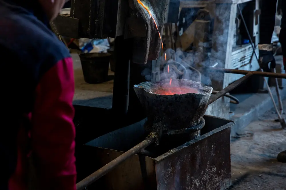
Cold Chamber Charging
Molten aluminium is ladled into the cold chamber shot sleeve from a holding furnace. The cold chamber is a separate cylinder — aluminium's high melting point (650°C+) makes hot chamber impossible.
2
High-Speed Injection
A hydraulic plunger drives the molten metal from the shot sleeve into the hardened steel die at 700–1,200 bar pressure. The die fills in milliseconds — too fast for air to escape, creating inherent gas porosity.
3
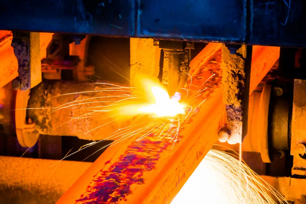
Intensification
After die fill, intensification pressure (up to 1,200+ bar) is applied to compact the solidifying metal, reducing shrinkage porosity while the part solidifies under extreme pressure.
4
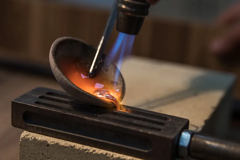
Solidification
Metal solidifies in typically 5–30 seconds depending on section thickness. The hardened H13 die (held at 150–250°C) extracts heat rapidly, producing a fine-grained as-cast structure.

5
Ejection
Die opens and ejector pins push the casting out. Gate, flash, and biscuit are trimmed. Cycle time: 30–120 seconds total. Typical output: 200–500 shots per 8-hour shift.
6
Post-processing
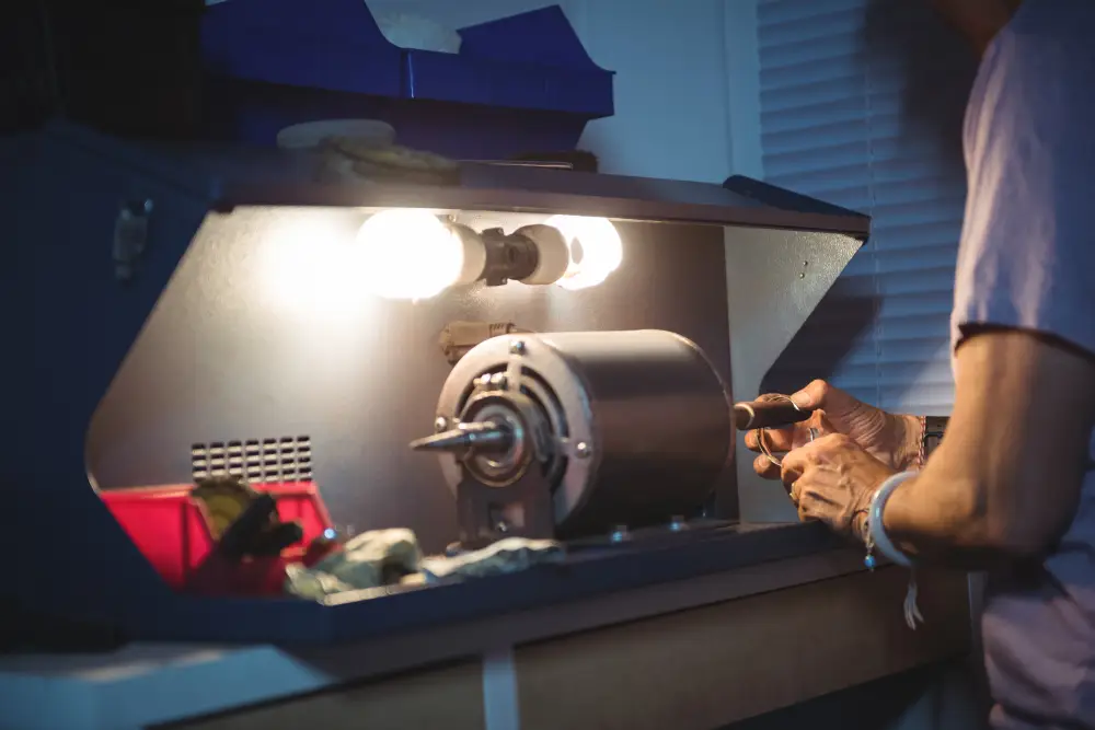
Gate vestige removal, deburring, inspection, stress relief (TS, 200–250°C only — no T6), machining, and surface treatment. Impregnation for pressure-tight applications.
Materials
Aluminium Alloys Suitable for High Pressure Die Casting
| ALLOY | NOMINAL COMPOSITION | SUITABILITY | NOTES |
|---|---|---|---|
| LM2 | Al-Si10Cu2 |
4 - Excellent
|
Excellent — most widely used HPDC alloy globally. Best castability for HPDC. |
| LM20 | Al-Si12 |
4 - Excellent
|
Excellent — eutectic alloy, best corrosion resistance of HPDC alloys. |
| LM24 | Al-Si8Cu3.5 |
4 - Excellent
|
Excellent — highest tensile and best machinability of standard HPDC alloys. |
| LM6 | Al-Si12 |
3 - Good
|
Good — LM20 preferred for HPDC, but LM6 castable. |
| LM25 | Al-Si7Mg0.5 |
3n - Not normally recommended
|
Not normally recommended — T6 not applicable to HPDC. Use GDC/LPDC for LM25. |
| LM9 | Al-Si12Mg0.5 |
n - Not recommended
|
Not recommended for HPDC per BS 1490 Table 8. |
| LM5 | Al-Mg5Mn0.5 |
2 - Fair
|
Fair — oxide inclusions make LM5 difficult in HPDC. |
| LM30 | Al-Si17Cu4.5 |
3 - Good
|
Good — only Group C alloy with positive HPDC rating. Hypereutectic piston alloy. |
Heat Treatment on High Pressure Die Casting Castings
Tolerances
High Pressure Die Casting Dimensional Tolerances — ISO 8062-3:2007
Dimensional Casting Tolerance Grade per ISO 8062-3:2007. High Pressure Die Casting achieves DCTG 6–9. Tolerances are symmetrically disposed (±half the total band) unless individually specified.
| NOMINAL DIMENSION | TOLERANCE RANGE | BEST (DCTG 6) | WORST (9) |
|---|---|---|---|
| up to 10mm | ±0.13-0.52mm | ±0.13 | ±0.52 |
| 10-25mm | ±0.15-0.58mm | ±0.15 | ±0.58 |
| 25-100mm | ±0.22-0.78mm | ±0.22 | ±0.78 |
| 100-250mm | ±0.31-1.0mm | ±0.31 | ±1.0 |
| 250-400mm | ±0.39-1.1mm | ±0.39 | ±1.1 |
| Parting line | Add 0.1-0.25mm | — | — |
| Wall thickness | One DCTG grade coarser per ISO 8062-3 | — | — |
Wall Thickness — One Grade Coarser per ISO 8062-3
Surface Finish
Per ISO 8062-3:2007 Clause 7: wall thickness tolerances are one DCTG grade coarser than the general stated DCTG. Account for this when specifying wall thickness tolerances on engineering drawings.
Machining Allowances (RMA) — ISO 8062-3 Annex B
| SURFACE TYPE | REQUIRED MACHINING ALLOWANCE |
|---|---|
| Small surfaces (≤100mm) | 0.5-1.0mm per face (RMAG A-B) |
| Medium surfaces (100 | 0.75-1.5mm per face (RMAG B-C) |
| Large surfaces (>300mm) | 1.0-2.0mm per face (RMAG C) |
| Bores and holes | 0.5-1.5mm on radius |
Design Guide
High Pressure Die Casting Design Rules — Wall Thickness, Draft & Tooling
Minimum Wall Thickness
| Section / Condition | Minimum Thickness |
|---|---|
| Minimum wall thickness(≤100mm) | 1.0–2.0mm — thinnest of all casting processes(≤100mm) |
| Recommended production wall | 2.0–4.0mm for consistent fill and mechanical properties (≤100mm) |
| Maximum practical wall (>300mm) | 12–15mm — porosity increases significantly with section thickness (>300mm) |
| Rib thickness | 0.5–0.8× adjoining wall thickness(>300mm) |
| Boss wall thickness | ≤2× boss diameter; boss wall = 0.6× boss diameter(>300mm) |
Draft AngleS
| Surface Feature | Required Draft |
|---|---|
| External surfaces (short draw ≤25mm)(≤100mm) | 0.5° min — finest draft of all processes(≤100mm) |
| External surfaces (medium draw 25–100mm) | 0.5°–1° (≤100mm) |
| External surfaces (long draw >100mm)(>300mm) | 1°(>300mm) |
| Internal surfaces (metal cores/slides) | 1°–2°(>300mm) |
| Textured surfaces | Add 1°–3° to base draft(>300mm) |
Draft Calculation
ToolinG
| Parameter | Details |
|---|---|
| Die material | H13 tool steel — hardened to 44–48 HRC, nitride coated for die soldering resistance |
| Machine type | Cold chamber — aluminium requires cold chamber; hot chamber only for zinc/magnesium |
| Tooling lead time | 8–16 weeks for complex tooling with slides and core pulls |
| Die life | 100,000–500,000 shots depending on alloy temperature and die cooling design |
| Tooling cost | Highest of all casting processes — typically 3–5× GDC tooling cost |
| Slides & cores | Metal side-actions and core pulls allow undercuts — adds significant cost |
Evaluation
Advantages & Limitations of High Pressure Die Casting
Advantages
- Thinnest walls achievable: 1.0–2.0mm — impossible in sand or gravity die casting
- Finest as-cast surface finish: Ra 0.8–3.2 µm — near machined quality
- Fastest cycle time: 30–120 seconds — highest production rates
- Lowest per-piece cost at high volumes (>10,000 pieces/year)
- Minimal machining stock (0.5–1.5mm per face)
- Consistent shot-to-shot quality in automated production
- Complex external geometry achievable with slides and core pulls
Limitations
- NOT normally heat-treatable to T6 — gas porosity causes blistering during solution treatment
- Highest inherent porosity of all casting processes
- Alloy choice restricted: primarily LM2, LM20, LM24
- Highest tooling cost (3–5× GDC tooling)
- Longest tooling lead time (8–16 weeks)
- Ejector pin marks and gate vestige on all HPDC castings
- Not suitable for structural safety-critical parts (unless Vacuum HPDC)
- Economical only at high volumes (typically >10,000 pieces/year)
- Maximum wall thickness ~15mm practical limit
Applications
Typical Applications — High Pressure Die Casting

HPDC Applications — Automotive & Electronics
| Industry | Typical Parts | Why High Pressure Die Casting |
|---|---|---|
| Automotive | Engine housings, transmission brackets, air intake manifolds, alternator housings, oil pump bodies | Thin-wall, high-volume, dimensional precision at automotive scale |
| Electronics | Laptop housings, 5G base station frames, heat spreaders, camera housings | Thin wall 1–2mm, fine surface finish, EMI shielding |
| Consumer Products | Door handles, window hardware, appliance components, power tool housings | High-volume economy, good surface for painting/plating |
| Telecommunications | Antenna housings, radio frames, connector bodies | Complex geometry, thin wall, tight tolerances |
| Electrical | Motor frames, connector housings, junction boxes, LED heat sinks | Volume production, consistent dimensions, thermal conductivity |
| Industrial | High-volume instrument housings, brackets, covers | Lowest per-piece cost at production volumes |
Frequently Asked Questions
Common Questions About High Pressure Die Casting
What is High Pressure Die Casting (HPDC)?
Why can't HPDC castings normally be T6 heat treated?
What alloys are used in HPDC?
What is the minimum wall thickness for HPDC?
What dimensional tolerances does HPDC achieve?
What is Vacuum HPDC?
When should I use HPDC instead of GDC or LPDC?
What causes ejector pin marks and gate vestiges in HPDC?