
- Home
- Design Advice
Design It Right
Before You Cut
Steel.

DFM Rule
Draft Angles
Sand Casting — External
1° – 3°
Pattern walls on cope and drag faces
Sand Casting — Internal / Cores
2° – 5°
Deeper draft needed for internal core faces
Gravity Die (GDC)
2° – 4°
Metal die requires more draft than sand
LPDC
2° – 4°
Consistent with GDC; inner surfaces 3°–5°
HPDC — External
0.5° – 2°
High pressure and smooth die surface allow shallower draft
HPDC — Internal
1° – 3°
Cores and deep pockets require increased draft

Why It Matters
Quick Reference — Draft by Depth
≤25 mm
Feature Depth
1° min
25–75 mm
Feature Depth
2° min
>75 mm
Feature Depth
3° min
Design This Way
- Apply draft to all walls parallel to the draw direction — external and internal
- Increase draft on deep pockets and narrow ribs beyond the minimum
- Note machined surfaces clearly — draft can be removed post-machining on datums and bores
- Agree draft direction with the foundry before finalising the parting line
Avoid This
- Zero-draft walls on non-machined surfaces — the part cannot be extracted cleanly
- Negative draft (reverse taper) — actively locks the casting into the tool
- Applying the same draft to internal and external surfaces — internal always needs more
- Forgetting draft on features designed in a different orientation to the main part
DFM Rule
Wall Thickness
Sand Casting
4–6 mm
Minimum for reliable fill; 5 mm recommended general
Gravity Die (GDC)
3–5 mm
Metal die conducts heat faster — 3.5 mm practical minimum
LPDC
3–4 mm
Controlled fill allows thinner sections reliably
HPDC
1.5–2.5 mm
High injection speed and pressure fill thin walls

Solidification Sequence Rule
Thick-to-Thin Transition Rule
Design This Way
- Target uniform wall thickness throughout — aim for variation <20% from nominal
- Use ribs to provide stiffness instead of increasing wall thickness
- Taper thick-to-thin transitions gradually over at least 3× the thickness change
- Core out thick sections — hollow bosses and pads rather than solid masses
Avoid This
- Abrupt junction of thin wall to thick flange — shrinkage porosity is almost certain
- Walls below process minimum — cold shuts and misruns will result
- Isolated thick sections surrounded by thin walls — "hot spot" with no feed path
- Uniform-thickness thinking from sheet metal — casting solidification is 3-dimensional
DFM Rule
Corner Radii & Fillets
Internal Fillet — Minimum
R 3 mm
Absolute minimum; R5 or greater strongly preferred
Internal Fillet — Recommended
R 5–8 mm
Prevents die chipping and sharp oxide formation in the casting
External Corner — Minimum
R 1.5 mm
Prevents die chipping and sharp oxide formation in the casting
Fillet at Rib Junction
0.5–1× wall thickness
Fillet radius = 0.5t to 1t where t = rib thickness

Fatigue Life Impact
Increasing an internal corner radius from zero (sharp) to R5 mm improves fatigue life by 20–40% in tested aluminium casting specimens — with no weight penalty and no tooling cost increase. It is the single cheapest design change with the highest mechanical return.
Hot Spot at Corner
A sharp internal corner creates a thermal hot spot — metal in the corner is surrounded on two sides by already-solidifying material, trapping heat. The last liquid metal to solidify shrinks, creating a micro-void or crack. A fillet distributes this zone over a curved surface, reducing peak temperature and allowing directional solidification away from the corner.
Design This Way
- Apply generous internal fillets everywhere — minimum R3, target R5 or greater
- At rib-to-wall junctions, fillet = 0.5× to 1× the wall thickness
- Break all external edges with at least R1.5 — no sharp arris on castings
- Where a sharp internal corner is functionally required, machine it in after casting
Avoid This
- Zero-radius internal corners — fatigue crack initiation is almost guaranteed
- Sharp rib-to-wall junctions — solidification stress concentration causes micro-cracking
- Inconsistent radii on the same surface — varies stress distribution unpredictably
- Specifying "break sharp edges" as a substitute for designed-in fillets
DFM Rule
Parting Line Design
The Core Principle
The parting line should follow the maximum cross-section of the part — the widest point when viewed in the draw direction. This minimises undercuts, simplifies tooling, and allows all surfaces to be drafted toward the parting plane. A poorly placed parting line multiplies tooling cost and reduces dimensional capability.
Flash & Fettling

Good Parting Line Practice
- Place at the maximum cross-section — the widest perimeter of the part in draw direction
- Keep parting line in a single plane wherever possible — stepped parting lines cost more
- Place on a non-cosmetic surface — parting line flash is visible and requires fettling
- Consider parting line position at the sketch stage — it's very difficult to move later
- Ask the foundry to mark the proposed parting line on your 3D model before tooling
Common Mistakes
- Placing the parting line on a sealing face, bearing surface, or cosmetic external face
- Designing features that force a stepped, angled, or curved parting plane
- Ignoring the parting line entirely and leaving it to the toolmaker — costly assumption
- Specifying tight tolerances across the parting line — it always introduces variability
Dimensional Note
DFM Rule
Ribs , Bosses & Pads
Ribs, bosses, and mounting pads are the features most commonly over-sized by designers unfamiliar with casting. A rib that is too thick relative to the wall it joins will create a shrinkage hot spot at the junction. A boss that is solid and thick will almost certainly contain internal porosity. Designing these features correctly adds stiffness and function at no weight or cost penalty.
Rib Thickness
0.5 – 0.8× wall
Rib thickness = 50–80% of the wall it joins. Never equal to or greater than the wall.
Rib Height Limit
≤ 5× rib thickness
Taller ribs need draft and are difficult to fill reliably. Maximum H/t ratio = 5.
Boss OD / Wall Ratio
≤ 2× wall thickness
Boss diameter should not exceed 2× the adjacent wall. Core out large bosses.
Boss — Coring
Core to 75% depth
Solid bosses shrink. Core out to leave a 1.5–2 mm base wall — removes hot spot.

Stiffness without Mass
Rib Design Rules
- Rib thickness = 0.6× wall for best results — thin enough to avoid hot spot, thick enough to fill
- Space parallel ribs at minimum 2× rib thickness apart — metal must flow between them
- Core out all bosses over 15 mm diameter — this is the single most effective porosity prevention step for bosses
- Add a generous fillet at every rib-to-wall junction — minimum R = 0.5× rib thickness
Common Mistakes
- Making ribs the same thickness as the wall they stiffen — guaranteed hot spot
- Intersecting ribs at right angles without adequate metal — creates a node hot spot
- Solid tall bosses — internal shrinkage is almost certain without coring
- Mounting pads machined directly into raw wall surfaces — always add a cast-in pad with machining allowance
DFM Rule
Machining Allowances
Sand Casting
2.5 – 5 mm
Largest allowance — widest casting tolerance (CT8–CT10)
Gravity Die (GDC)
1.5 – 3 mm
Better dimensional consistency; CT6–CT8 typical
LPDC
1.0 – 2.5 mm
Tighter process — CT5–CT7; smaller allowance needed
HPDC
0.5 – 1.5 mm
Best dimensional accuracy; CT4–CT6; minimum allowance

ISO 8062 Casting Tolerances
| PROCESS | CT GRADE |
|---|---|
| Sand Cast | CT8–CT10 |
| GDC | CT6–CT8 |
| LPDC | CT5–CT7 |
| HPDC | CT4–CT6 |
Hard Anodising — Special Case
If the finished component will be hard anodised (Type III), the coating grows ~50% outward. A 50 µm coating adds ~25 µm per face. Specify a “pre-anodise” dimension on all tolerance-critical features so the machining drawing reflects the dimension before coating, not after. This is a very common oversight causing fit failures after processing.
On the Drawing
- Show both the casting dimension (with allowance) and the machined final dimension — two dimension sets
- Mark machined surfaces with the standard machining symbol and Ra requirement
- Add datums — state which cast surface or machined feature is the datum for all machined dimensions
- Specify the casting tolerance standard (ISO 8062 CT grade) on the title block
Common Drawing Errors
- Providing only the final machined dimension — the foundry has no reference for stock allowance
- Applying the same allowance regardless of process — wastes material and machining time
- No datum defined — machinist cannot locate the part consistently
- No machining symbols — foundry cannot identify which surfaces need allowance
DFM Rule
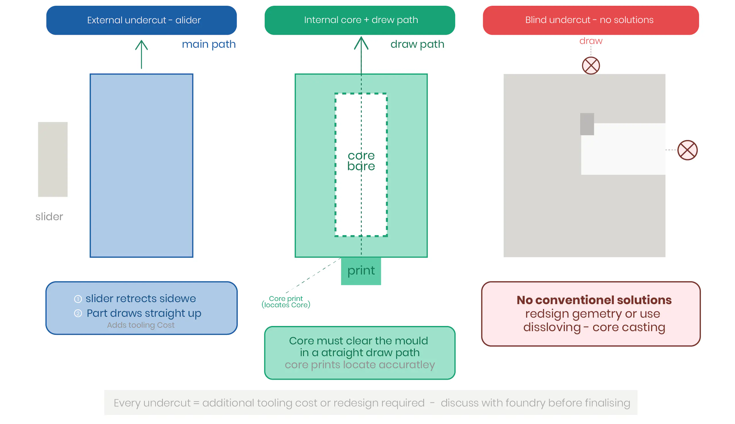
Undercuts & Cores
Sand Casting
Most flexible
Sand cores can form almost any internal geometry — but cores must be supported and extractable
GDC / LPDC
Side actions + cores
External undercuts via slides; internal via sand or metal cores that can be pulled
HPDC
Sliders for external
No sand cores possible; internal undercuts extremely limited — plan geometry carefully
Dissolving-Core
Blind undercuts ✓
Complex hollow internal geometries impossible by conventional means — core dissolved in water
Advanced Capability — Dissolving-Core Casting
If Your Internal Geometry Has No Conventional Solution
Core Design Requirements
Design Principles
- Identify all undercuts early — mark them on the 3D model and discuss with the foundry before tooling
- Redesign external undercuts into draft-able features where possible — avoids sliders
- Ensure internal cores have both a print (support) and a draw path — core must be removable
- For blind internal geometry — consider dissolving-core casting as the right solution
Common Problems
- Designing internal passages that loop back on themselves — no extraction path for conventional core
- HPDC designs with complex internal geometry — the process cannot accommodate internal cores
- Undercuts on mating faces — slider witness marks fall on functional surfaces
- Assuming what is possible in 3D CAD is possible in casting — they are different constraints
DFM Decision 08
Choosing the Right Process
Process selection is a design decision — not just a commercial one. The process you choose determines achievable wall thickness, tolerance, surface finish, tooling cost, and minimum economic order quantity. Get this right at concept stage.
Process 01
Sand Casting
- Min Wall
- Tolerance
- Surface Finish
- Tooling Cost
- MOQ
- Weight Range
- 4–6 mm
- CT8–CT10
- Ra 6.3–25 µm
- Lowest
- 1 piece
- 0.1 – 500 kg
Best for
- Low volume
- Complex geometry
- Large parts
- Prototypes
Process 02
Tilt GDC
- Min Wall
- Tolerance
- Surface Finish
- Tooling Cost
- MOQ
- Weight Range
- 3–5 mm
- CT6–CT8
- Ra 3.2–6.3 µm
- Medium
- 50–200 pcs
- 0.05 – 50 kg
Best for
- Med volume
- Low porosity
- Structural parts
- Heat treatable
Process 03
LPDC
- Min Wall
- Tolerance
- Surface Finish
- Tooling Cost
- MOQ
- Weight Range
- 3–4 mm
- CT5–CT7
- Ra 1.6–3.2 µm
- Medium–High
- 200–500 pcs
- 0.5 – 30 kg
Best for
- Structural
- Safety-critical
- Thin walls
- High density
Process 04
HPDC
- Min Wall
- Tolerance
- Surface Finish
- Tooling Cost
- MOQ
- Weight Range
- 1.5–2.5 mm
- CT4–CT6
- Ra 0.8–1.6 µm
- Highest
- 1000+ pcs
- 0.01 – 25 kg
Best for
- High volume
- Thin wall
- Tight tolerance
- Best surface
Not sure which process fits your part?
DFM Decision 09
Alloy Selection Guide
Alloy selection affects castability, mechanical properties, corrosion resistance, machinability, and heat treatability. This guide matches the most common LM alloys to their primary application requirements.
| Alloy | Designation | Strength | Corrosion | Castability | Heat Treat | Best Process | Primary Use |
|---|---|---|---|---|---|---|---|
| LM2 | Al–Si10Cu2Fe | No | HPDC | General purpose die casting, enclosures | |||
| LM4 | Al–Si5Cu3 | T5 / T6 | SAND GDC | Versatile engineering, housings, brackets | |||
| LM5 | Al–Mg5Si | No | SAND GDC | Marine, chemical exposure, food equipment | |||
| LM6 | Al–Si12 | No | SAND GDC LPDC | Pump bodies, marine, thin sections, complex shapes | |||
| LM13 | Al–Si12CuMgNi | T5 | GDC LPDC | Pistons, wear surfaces, elevated temperature | |||
| LM16 | Al–Si5Cu1Mg | T5 / T7 | SAND GDC LPDC | Pressure-tight, structural, impact-resistant | |||
| LM25 | Al–Si7Mg | T4 / T5 / T6 | SAND GDC LPDC | Premium structural, automotive, aerospace-grade | |||
| LM26 | Al–Si9Cu3Mg | T5 | GDC LPDC | Automotive — high strength, wear resistant |
Before You Send the Drawing
DFM Self-Check Checklist
Geometry
- Draft angles applied to all surfaces parallel to draw direction — internal and external
- Internal fillets ≥ R3 mm on all internal corners and rib junctions
- Wall thickness meets minimum for chosen process; no wall below minimum anywhere
- Thick-to-thin transitions tapered — no abrupt step changes in wall thickness
- Bosses cored out where diameter exceeds 15 mm
- Rib thickness ≤ 80% of the wall they join
Drawing & Tolerances
- Machining allowance added to all surfaces to be finish-machined — pre- and post-machine dimensions both shown
- Machined surfaces marked with surface finish symbol and Ra requirement
- Datums defined — machining datum surface clearly identified
- CT grade specified on title block (ISO 8062) or casting tolerances called out explicitly
- Tight tolerances not placed across parting line — move critical dimensions to single mould half
Process & Material
- Casting process confirmed — wall thickness, volume, and tolerance are compatible
- Alloy specified — correct LM grade for strength, corrosion, heat treatment, and process requirements
- Heat treatment specified if required — T4, T5, T6, or T7 with hardness or mechanical property requirement
- Surface coating considered — anodise allowance on drawings if hard anodise specified
- 3D CAD file ready — STEP or IGES format, solid model, no open surfaces
Free Service
Send Us Your Design for a DFM Review
- No commitment required — the review is free
- STEP, IGES, STL, PDF or DXF accepted
- Turnaround typically 2–3 business days
- Marked-up CAD or annotated PDF returned
- Alloy and process recommendation included
- Applicable to new designs and existing parts
The Cost of Getting It Wrong
A pattern revision after tooling is cut costs 20–60% of original tooling cost. A casting reject rate of 15% on a production run often traces back to a design decision made in the first week of a project. A 30-minute DFM conversation at concept stage eliminates most of this risk entirely.
Also Available
Prototype Before Committing